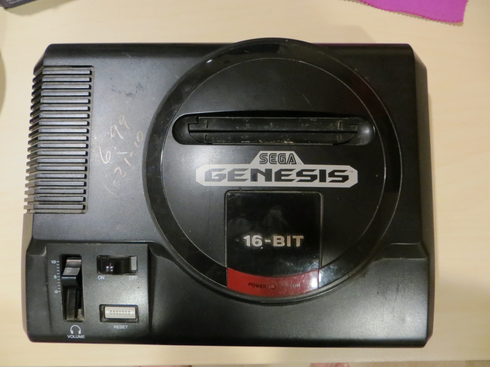
Been working on another site, http://retrogame.cyberphreak.com/ which follows my latest hobby, retrofitting old video game systems with Raspberry Pi computers. I will be mirroring my posts on this page. Now, the Tiger Game.com:
Game.com
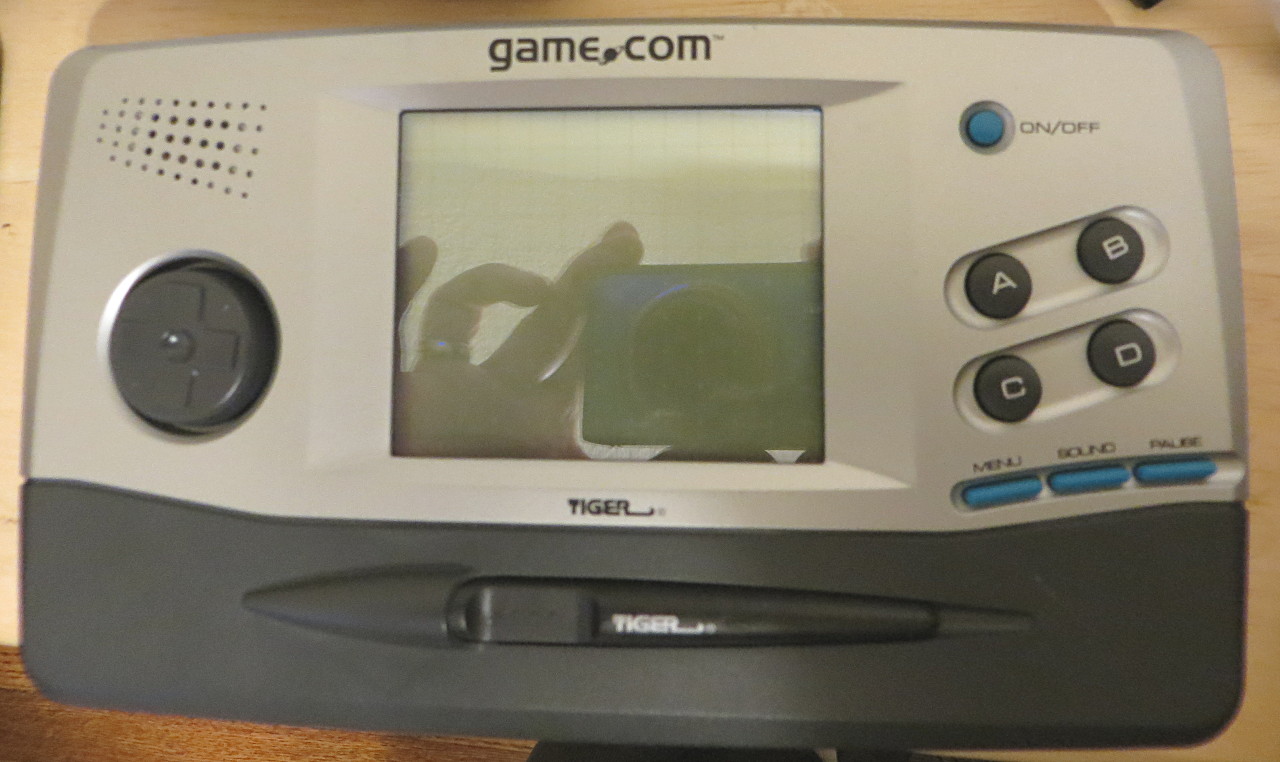
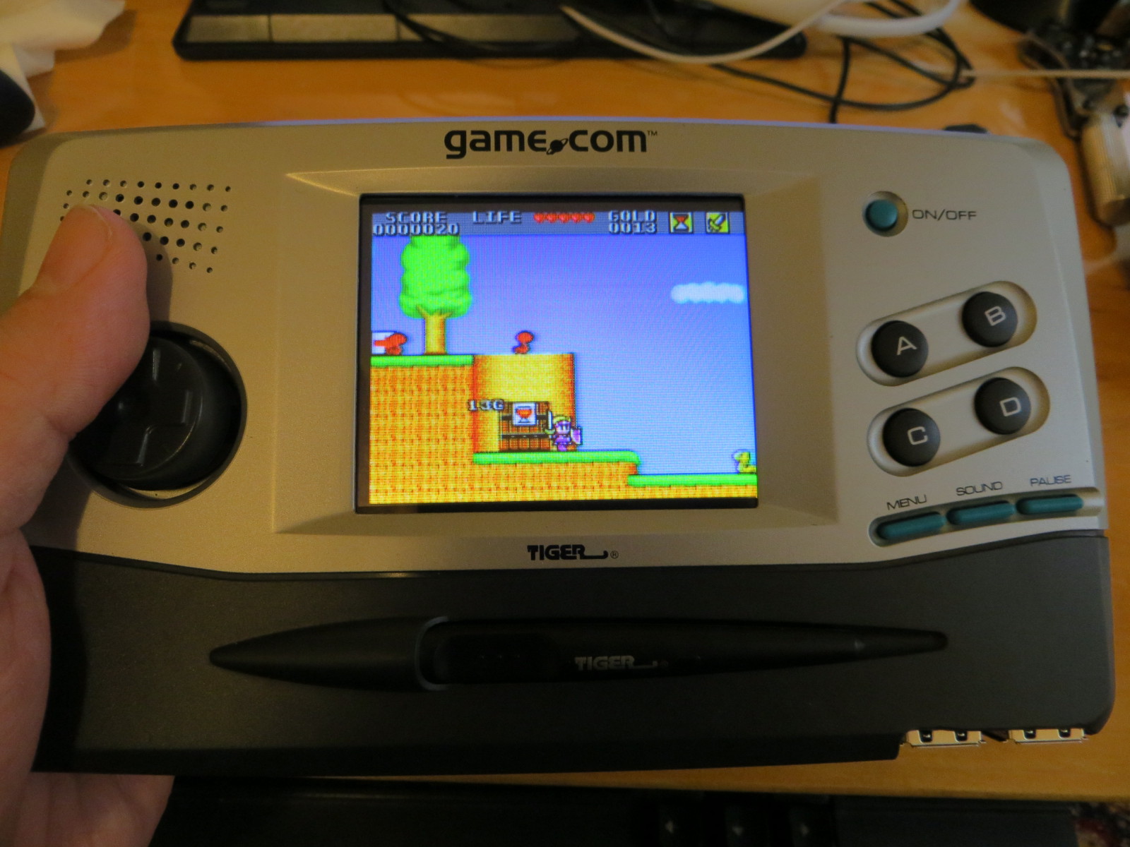
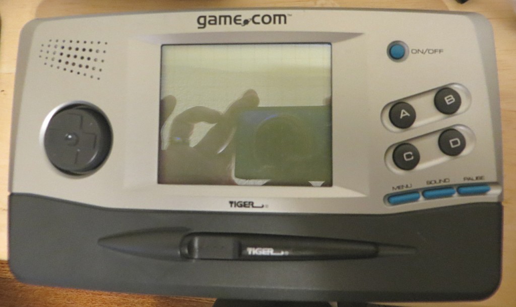
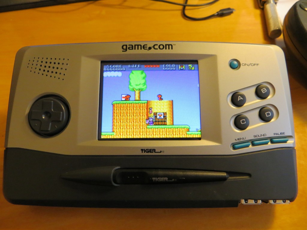
Ah, the Game.com, pronounced game com, no dot. It was a handheld system from 1997, made by Tiger Electronics. This was their second cartridge based system. The reviews for it are pure comedy on Youtube. The screen is totally terrible, but, look at that case design. My younger brother was impressed with my Atari Lynx retrofit, so he came up of the idea of making a system out of the technical abortion of the Game.com. The button layout is perfect, and the screen is a 3.5″ 4:3 screen, and, best of all, cheap on eBay.
Check out this and this video for more information.
From what I can tell, no one has attempted this modification, and I can’t even find a tear down of the system online. I believe less than 500,000 units were sold. This tear down and retrofit will be based on the original Game.com. There is a pocket version as well, but I don’t think it will have the space I need to work with.
Materials Needed:
Tiger Game.com, original, with two slots. Not much difference in price between working and not working. A working one with a good speaker is preferable.
Raspberry Pi 2 with up to a 32g microSD card for the operating system and games.
3.5″ LCD auto backup camera display, with composite input. I actually tried doing my previous mod with a SPI display for the Pi, and was very disappointed. There is a reason every mod you see online uses this display. If you have patience, you can get a screen for less than $15 from China. The specs say 6 to 32V input, but it runs just fine on 5V. All of my mods will use this screen.
USB gamepad. I went with a Buffalo Classic USB controller. Has all the buttons that I need, and I will use all of them.
The printed circuit board inside is pretty small and single sided, so easy to integrate. There are ways to plug directly into the Pi, but, this ends up costing a lot more than just hacking a USB game pad.
Wire. 26 AWG is fine. You can use single conductor or multi-conductor. Go with colors you can remember and make logical sense, like red for 5V line, black for ground, yellow for video, etc.
Tools needed: See this page.
The Tear Down:
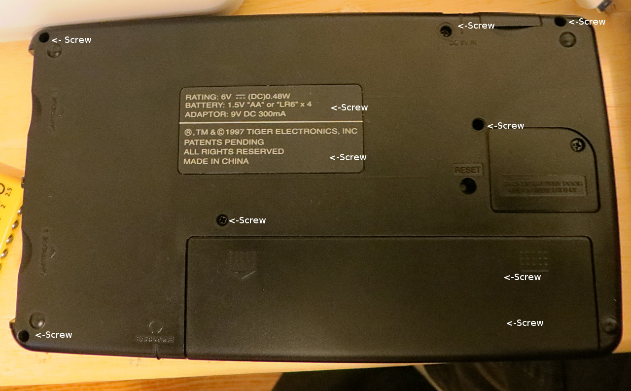
The unit, as shipped from an honest seller from eBay, is in great cosmetic shape. There are no scuffs or scratches that I can see. The screen is basically shot, with many missing horizontal lines. However, the first thing I am removing and replacing is the screen. It looks very much like someone got this for a Christmas present and tossed it in a drawer 18 years ago. This thing is held together by more freaking screws than I have ever seen in such a small piece of electronics. In the end, I had to remove 38 (!) screws. As a comparison, my Lynx is held together with 4 screws. This is a sign that this unit was designed with cheap labor in mind. In addition, there are 4 circuit board inside as well. The motherboard, the joypad board, the control button board, and the LCD controller board. Again, the Lynx has only 1 board, with everything attached.
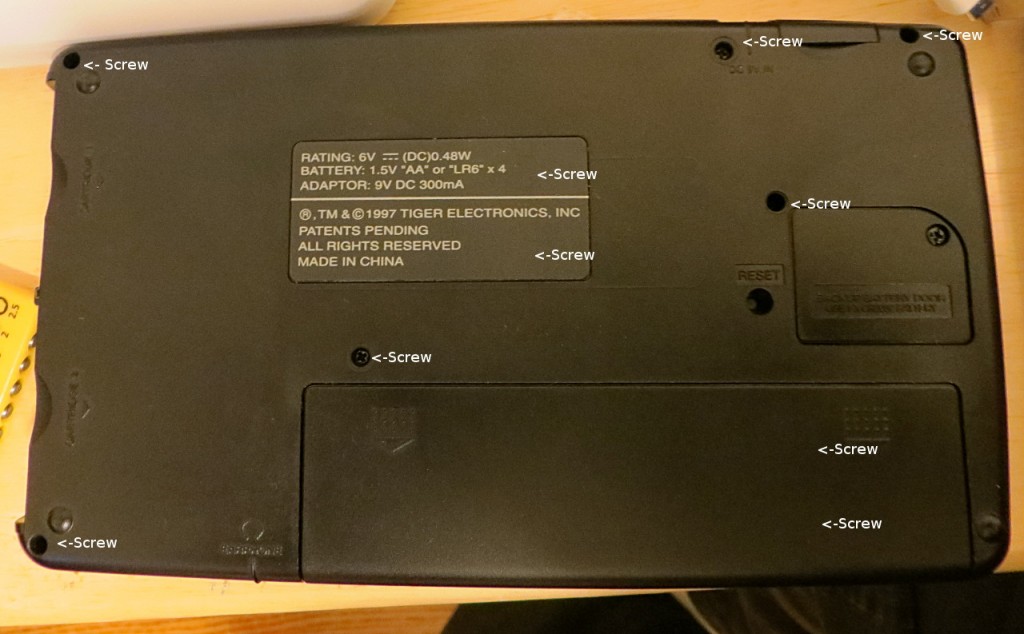
As you can see, the back alone is held on by 9 screws. When those are out, you need to pop the snap connectors around the sides of the Game.com. Once opened you are greeted by:
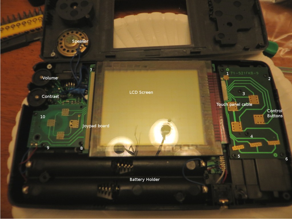
Another 10 screws. On the left, you can just see part of the motherboard. From left to right, you can see the joypad board, then the LCD screen, and to the right, another board with the control button contacts. Everything is pristine in this unit, indicating little or no use. My well loved Lynx had a lot of dirt, wear, and DNA inside.
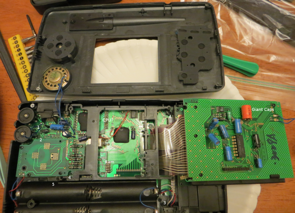
Clipping two wires allows the LCD screen to be flipped out the the way, revealing several things: 5 more screws, some giant capacitors, and the crudely installed CPU and RAM chips. The black stuff you see is a type of epoxy, you only usually see it with the cheapest of electronics. It is messy to use and labor intensive. The LCD interfaced via a pin header, the touch is through the flex cable. Why there are giant capacitors is beyond me. The screen must be electrically noisy, so they needed that for filtering?
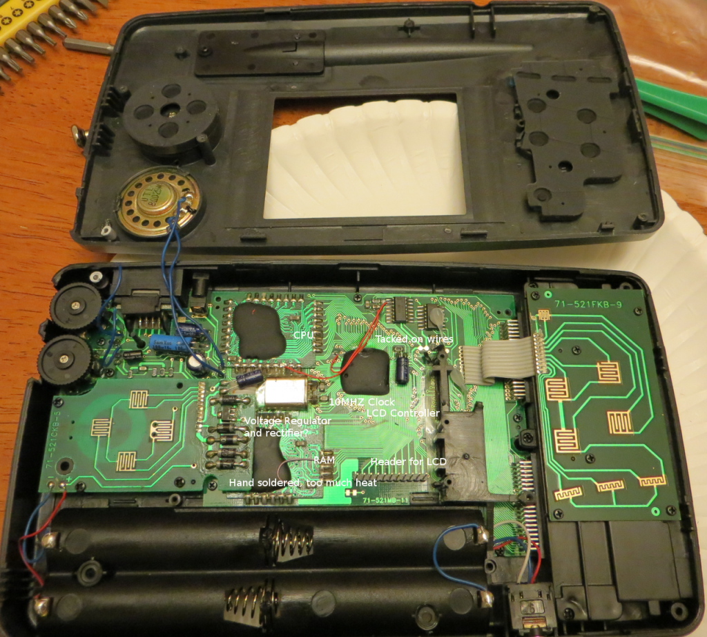
Here is the most of the main board revealed. It does reveal a lot to someone with 10 years of being a manufacturing engineer for an electronics company:
The CPU and RAM are hand soldered in place. There are 2 mysterious jumper wires (probably added when some trace failed). There are signs of cold solder joints and too much heat applied on the joypad/power regulator board. A lot more hand soldering than what is typical. Again, my old Lynx DID have some last minute modifications, but most of the board (90% or so) was surface mount electronics, thus done with ‘pick and place’ machines. A lot of this was done by hand…which is pretty typical of mid to late 90’s Chinese electronics. Though, the gold plating on the joypad and control buttons is quite thick and shows no signs of wear. The CPU must been clocked at 10Mhz, which is really pathetic on 8 bit processor from 1997. This thing must of been a bear to program for. A typical modem from this time period would probably have more computing power. I have a feeling the LCD controller is also the graphics chip as well.
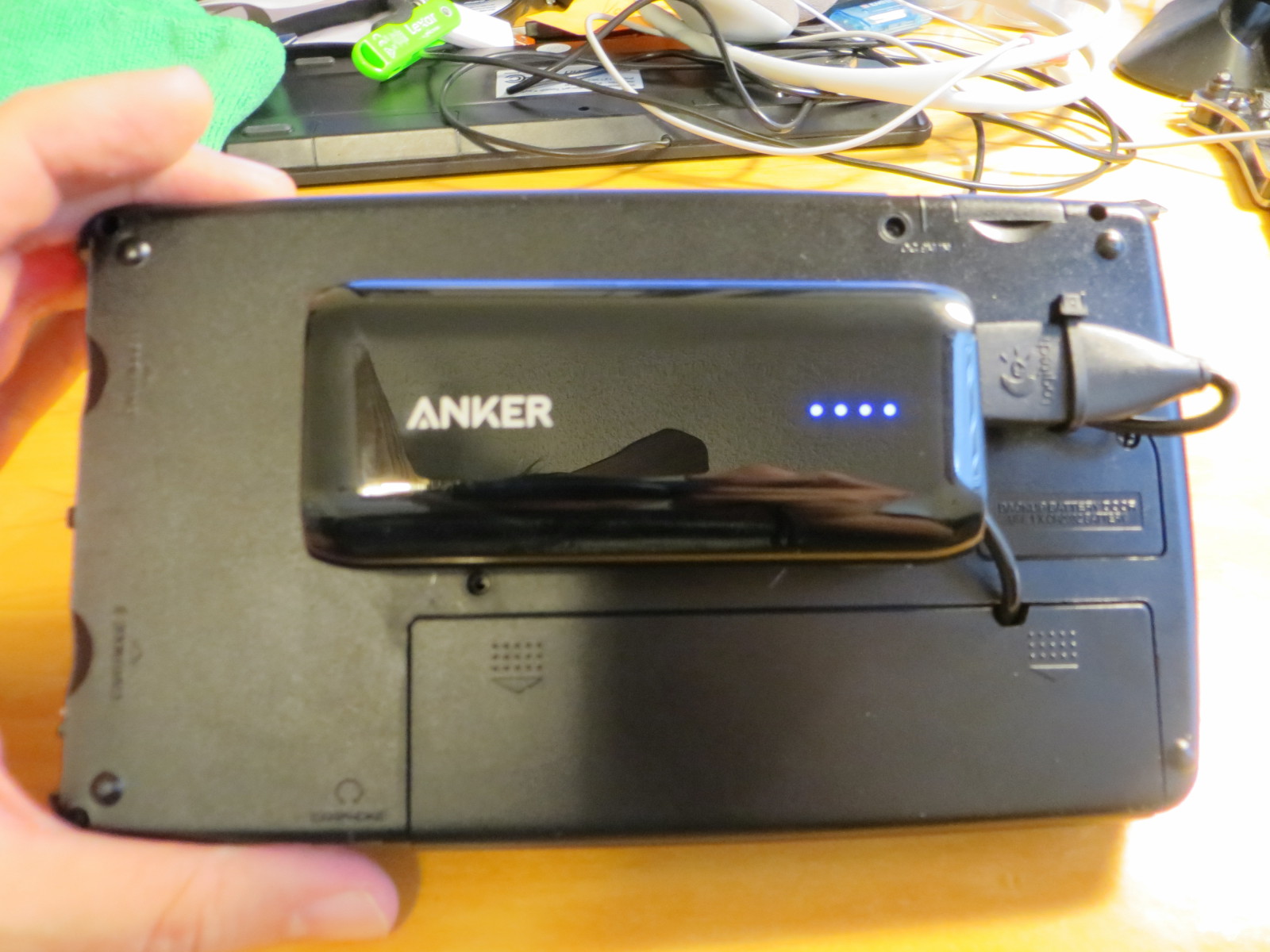
I’ll take better photos later, but here is the final result:


In the end, I had to cut out the battery holder. I replaced the contrast control with an on/off switch. The 5V cell phone charger battery back is hot glued to the back. They system works fine, but the ergonomics is just terrible and the d-pad is too mushy for practical use. When I tear this unit apart for cannibalizing, I will take internal photos to show what I did, and why. I am tempted to replace the d-pad with an analog stick, but the slab like construction of the game.com makes it too uncomfortable to hold for long term playing. The guts will be reborn in a Retro Game Gear/Nomad conversion.